Flash Tasmota
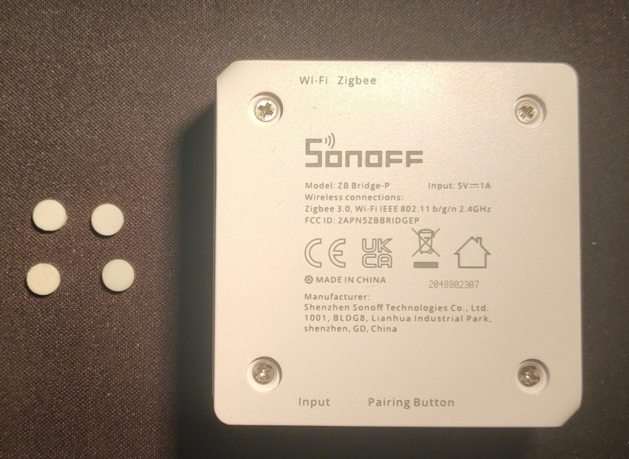
Step 1: Open ZbBrige Pro
 c
cRemove the rubber feets by using e.g. a scalpel at the bottom and unscrew the 4 small phillips screws beneath.
Step 2: Prepare board
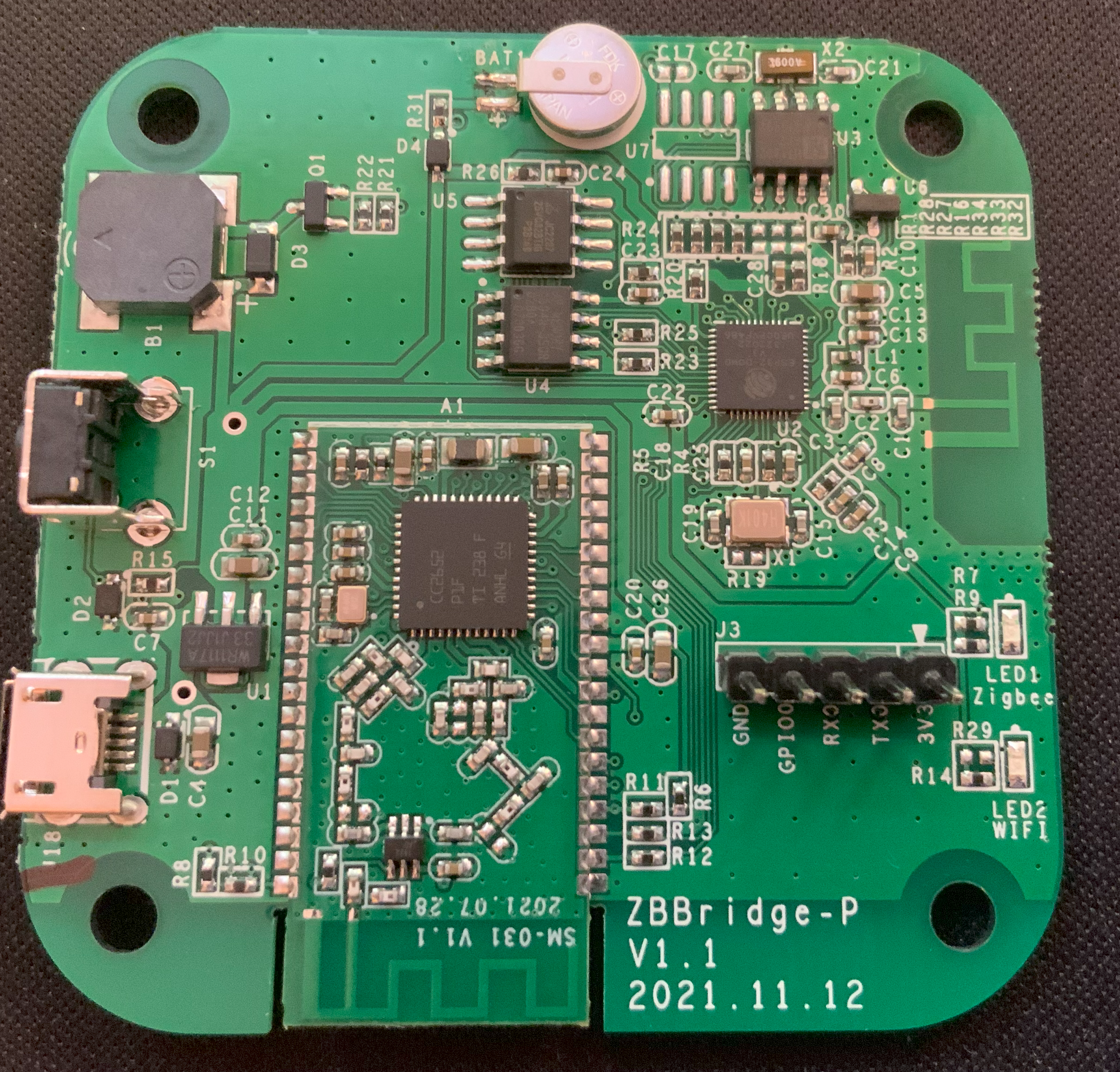
Solder 5 pins to the GND, GPIO0, RX,TX and 3V pinholes.
Step 3: Connect USB-to-TTL adapter
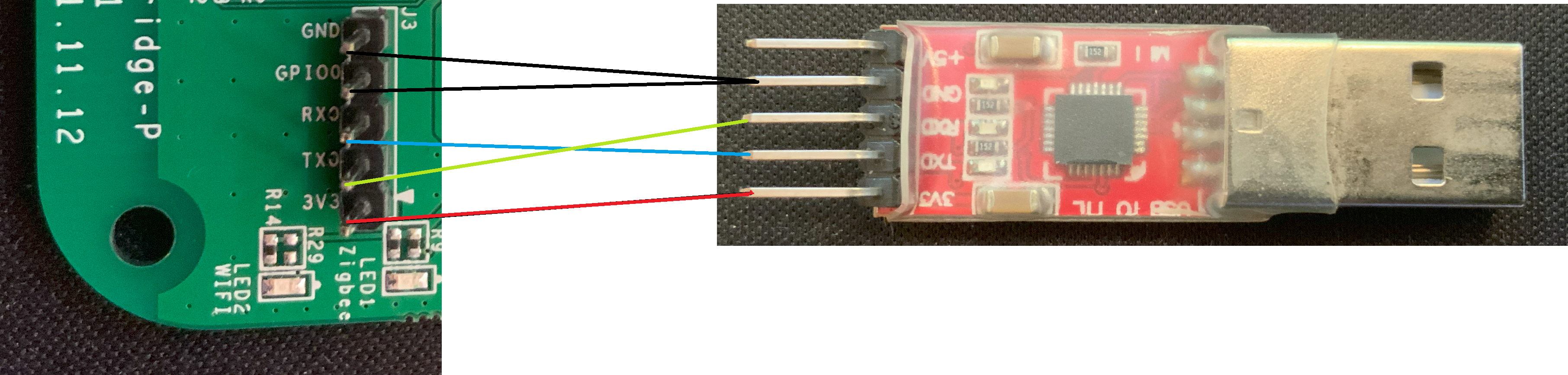
Connect using the following layout:
| ZbBridge | USB-to-TTL adapter |
| 3V3 |
3V3 |
| TX | RX |
| RX | RX |
| GPIO0 | GND |
| GND | GND |
Step 4: Flash Tasmota
Option 1: Webinterface
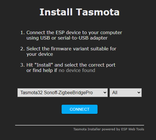
Go to the Tasmota install website and select the options Tasmota32 Sonoff-ZigbeeBridgePro and All, press connect and flash the firmware.
Option 2: Manual install via Tasmotizer (not verified)
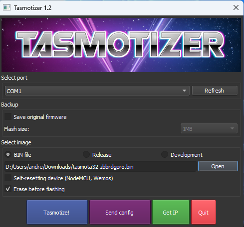
Download the newest version of the Tasmota firmware for Zigbee Bridge Pro and flash using the Tasmotizer application (tasmotizer-1.2.exe).
(Used version at date of creation: tasmota32-zbbrdgpro.bin)
Step 5: Flash ZigBee Coordinator
Plug in the device and head over to the Tasmota web interface. Then continue to Consoles > Berry Scripting console and input the following to very the flash files for the ZigBee Coordinator chip:
import sonoff_zb_pro_flasher as cc
cc.load("SonoffZBPro_coord_20220219.hex")
cc.check()
After getting a positive verification response contine to flash with the following command:
cc.flash()Now the Tasmota will become unresponsive for approximately 5 minutes, after that yet again a positive response should appear in the console (you might need to reload the website). Then restart the Tasmota device and head into the normal console, there should be messages regarding the ZigBee device now.
Step 6: Configure template
As a last step go to Configuration > Auto configuration and select and apply the Sonoff ZBPro configuration.
Credits
I followed Julian Decker's installation guide closely for the most parts, so have a look there if you need more detailed information.
No Comments