Smart Home
Information related to smart home software and hardware.
- Hardware
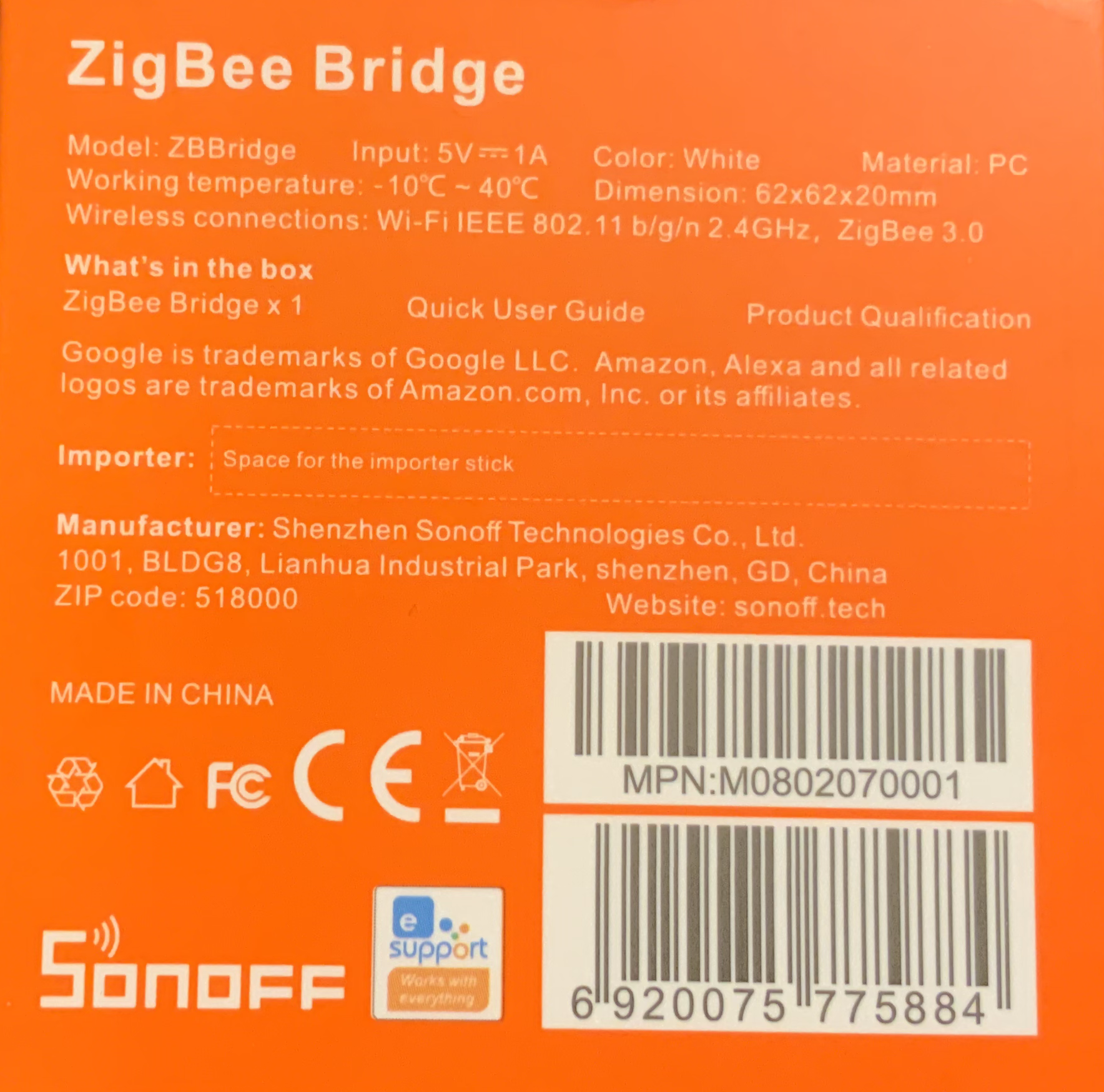
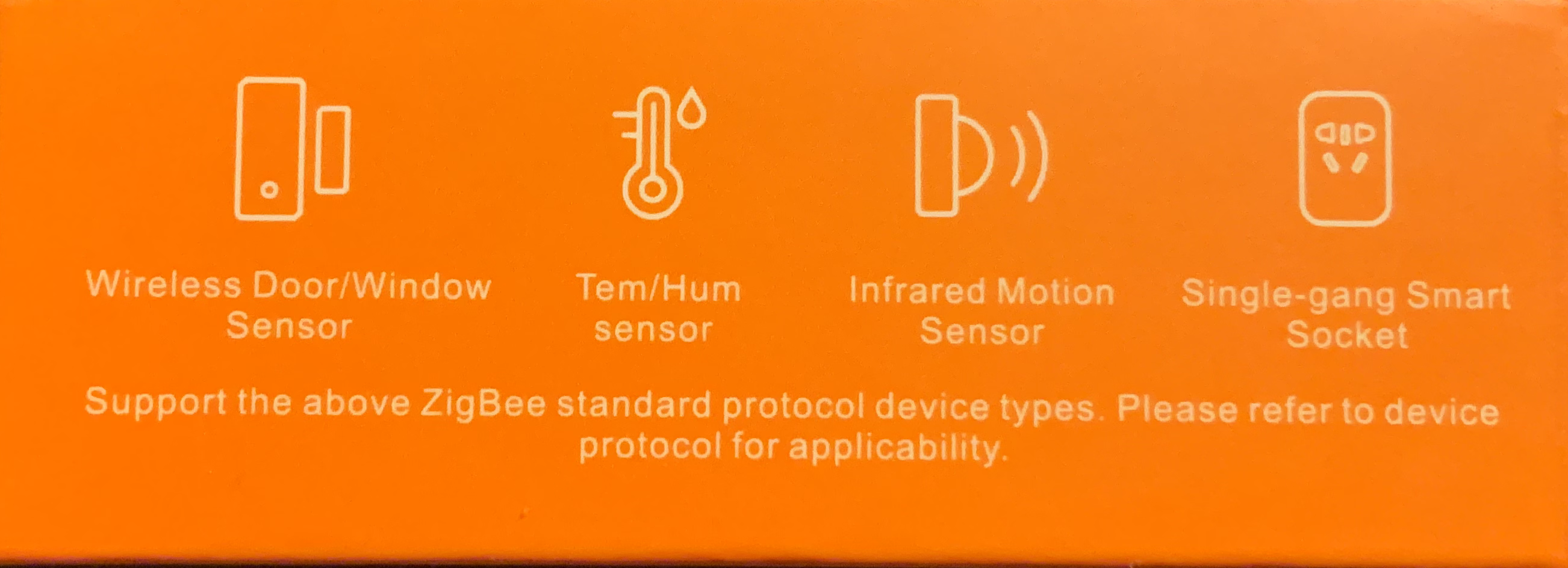
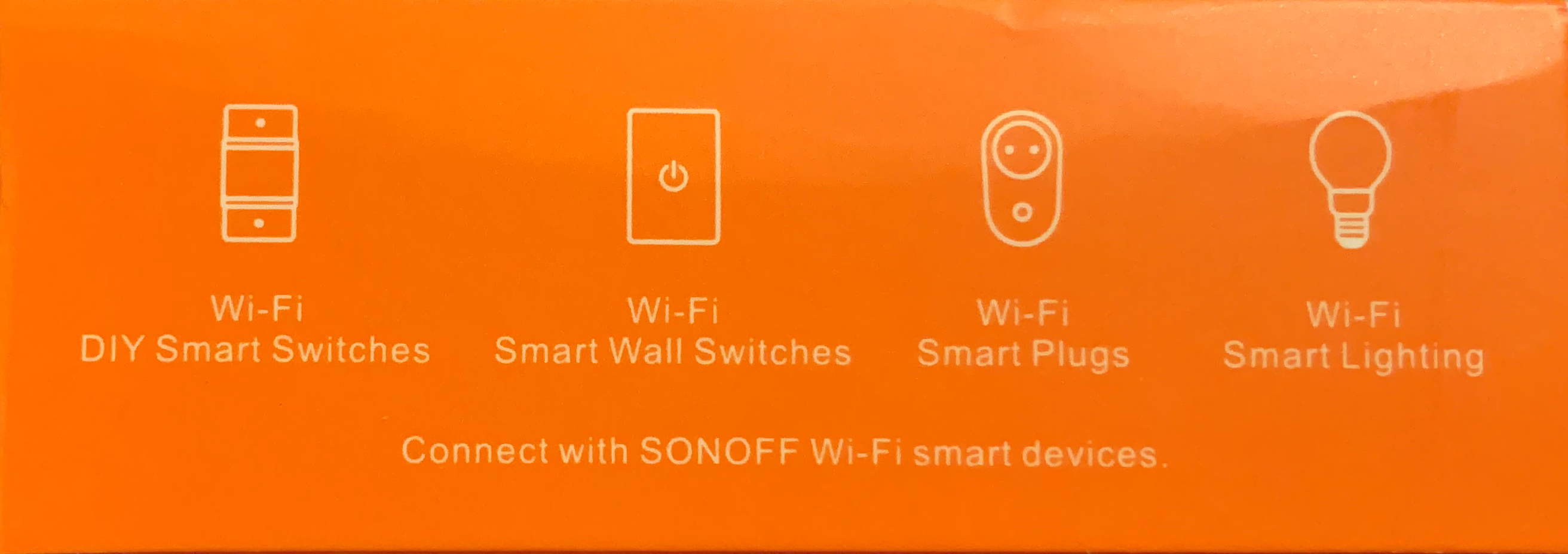
- Sonoff ZBridge
- Sonoff ZBridge Pro
- Sonoff ZigBee Sensors
- SNZB-01 - Wireless Switch
- SNZB-02 - Sonoff Temperature and Humidity Sensor
- SNZB-04 - Wireless Door/Window Switch
- Aqara ZigBee Sensors
- WSDCGQ11LM - Temperature and Humidity Sensor
- WSDCGQ11LM - Wireless Mini Switch
- WXKG03LM - Wireless Remote Switch (Single Rocker)
- Smart Meter
- Watermeter
- Kostal photovoltaic system
- Sunways NT4000
- WLED - LED controller
- Tasmota
- Tuya
- IR Receiver
- Onestyle SD-WL-02 Smart Plugs
- ZigBee2Mqtt
- ESPHome
- Grafana
- Smartmeter - SGM-D4
- Smart Thermostat
- eBUS
Hardware
Smart home hardware.
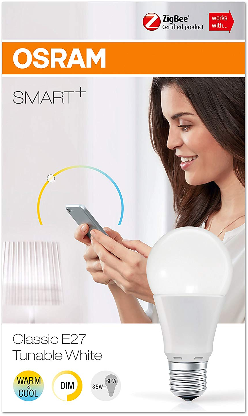
OSRAM Smart+ Classic E27 Tunable White
 Specs
Specs
- Communication: ZigBee
- Socket: E27
- Power consumption: 8.5W
- Color temperature range: 2700K - 6500K
- Lifespan: 15.000h
- Operation temperature: -20°C - 40°C
Available parameters
{
"Device":"0xEC24",
"Name":"osram2",
"Hue":0,
"Sat":0,
"X":24939,
"Y":24701,
"CT":370,
"ColorMode":2,
"RGB":"FFFFFF",
"RGBb":"FFFFFF",
"Endpoint":3,
"LinkQuality":97
}| Parameter | Description | Possible values |
| CT | Color temperature | 153 - 500 (Warm: 500, Normal: 370, Cold: 153) |
ESP32
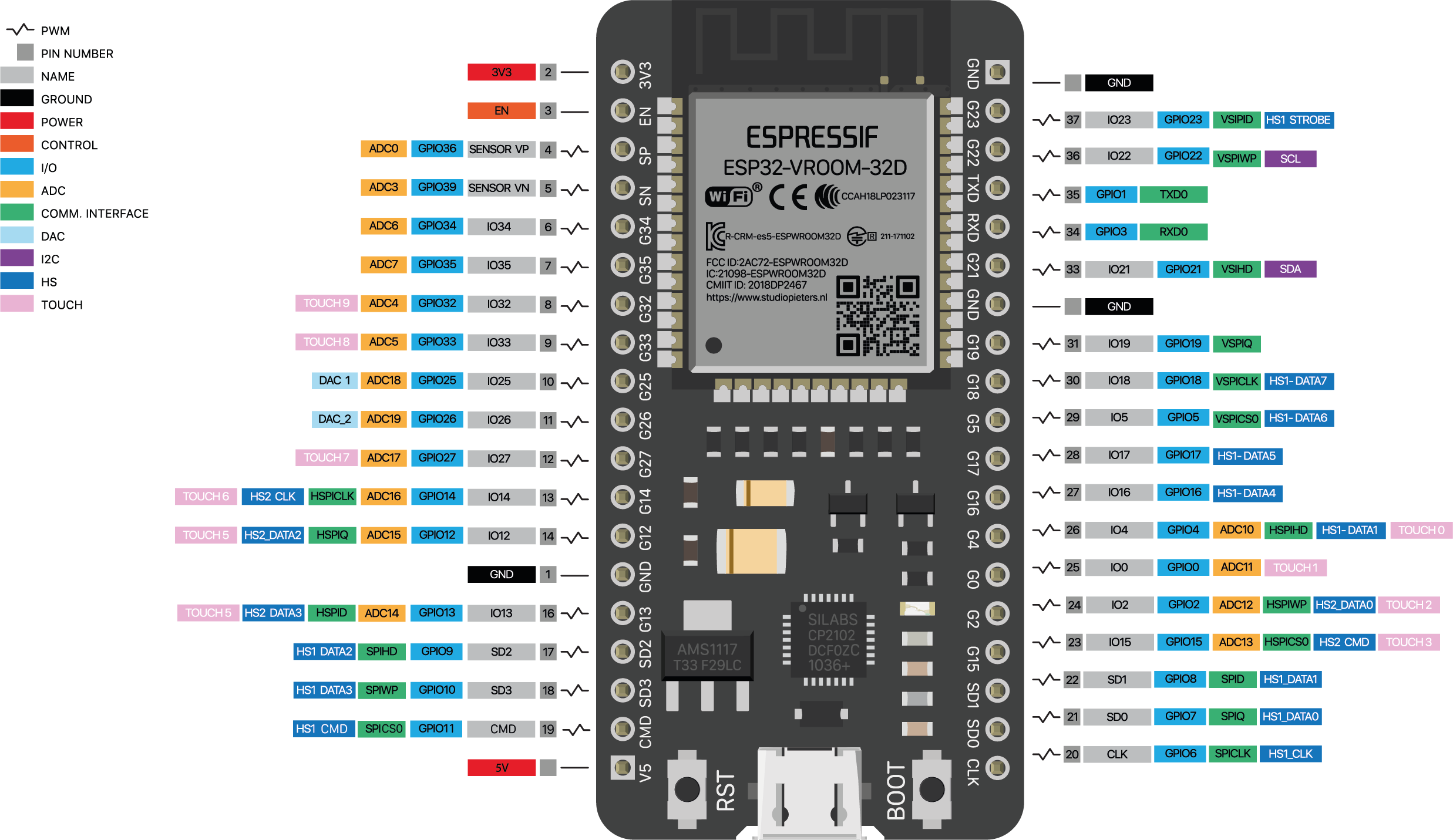
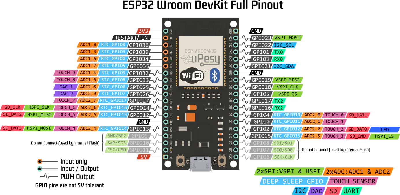
ESP-WROOM-32 (38pin)
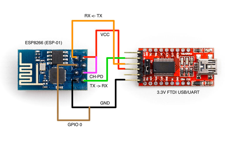
ESP8266
FTDI Programmer
Sonoff ZBridge
Sonoff Zigbee to Wifi bridge
Sonoff ZbBridge Rules
Rule1
on ZbReceived#osram1#Power do publish stat/andreas/zigbee/osram1/power %value% endon
on ZbReceived#osram1#Dimmer do publish stat/andreas/zigbee/osram1/dimmer %value% endon
on ZbReceived#osram2#Power do publish stat/andreas/zigbee/osram2/power %value% endon
on ZbReceived#osram2#Dimmer do publish stat/andreas/zigbee/osram2/dimmer %value% endon
on ZbReceived#osram3#Power do publish stat/andreas/zigbee/osram3/power %value% endon
on ZbReceived#osram3#Dimmer do publish stat/andreas/zigbee/osram3/dimmer %value% endon
on ZbReceived#osram4#Power do publish stat/andreas/zigbee/osram4/power %value% endon
on ZbReceived#osram4#Dimmer do publish stat/andreas/zigbee/osram4/dimmer %value% endonRule2
on ZbReceived#sonoff_door_sensor#Contact do publish stat/andreas/zigbee/sonoff_door_sensor/open %value% endon
on ZbReceived#light_sensor#Illuminance do publish stat/andreas/zigbee/light_sensor/illuminance %value% endon
on ZbReceived#temp_sensor_outdoor#Temperature do publish stat/andreas/zigbee/temp_sensor_outdoor/temperature %value% endon
on ZbReceived#temp_sensor_outdoor#Humidity do publish stat/andreas/zigbee/temp_sensor_outdoor/humidity %value% endon
on ZbReceived#temp_sensor_outdoor#Pressure do publish stat/andreas/zigbee/temp_sensor_outdoor/pressure %value% endon
on ZbReceived#temp_sensor_indoor#Temperature do publish stat/andreas/zigbee/temp_sensor_indoor/temperature %value% endon
on ZbReceived#temp_sensor_indoor#Humidity do publish stat/andreas/zigbee/temp_sensor_indoor/humidity %value% endon
on ZbReceived#temp_sensor_indoor#Humidity do publish stat/andreas/zigbee/temp_sensor_indoor/humidity %value% endon Rule3
on ZbReceived#sonoff_small_button_1#Power do publish stat/andreas/zigbee/sonoff_small_button_1/click %value% endon
on ZbReceived#aqara_big_button_1#Click do publish stat/andreas/zigbee/aqara_big_button_1/click %value% endon
on ZbReceived#aqara_button_1#Click do publish stat/andreas/zigbee/aqara_button_1/click %value% endon
on ZbReceived#aqara_button_2#Click do publish stat/andreas/zigbee/aqara_button_2/click %value% endon
on ZbReceived#aqara_button_3#Click do publish stat/andreas/zigbee/aqara_button_3/click %value% endon
on ZbReceived#aqara_button_4#Click do publish stat/andreas/zigbee/aqara_button_4/click %value% endonSonoff ZbBridge Commands
ZbName
This command can be used to give nicknames to the zigbee devices to be used instead of their HEX-value names.
Example:
ZbName 0x8C19,osram_bulbThis gives the nickname osram_bulb to the devices identified by 0x8C19.
ZbSend
With this command you can send information in JSON format to a zigbee device.
Example:
ZbSend {"device":"osram_bulb","Send":{"AddGroup":100}}By using this command the zigbee device identified by osram_bulb is added to the zigbee group 100. You can also use the HEX-value device ID instead of the nickname.
Sensor
Packaging
 |
 |
 |
 |
Documentation
- Product Specification: sonoff-zbbridge-product-specification.pdf
- User Manual: sonoff-zbbridge-user-manual.pdf
- Quick Start Guide: sonoff-zbbridge-quick-user-guide.pdf
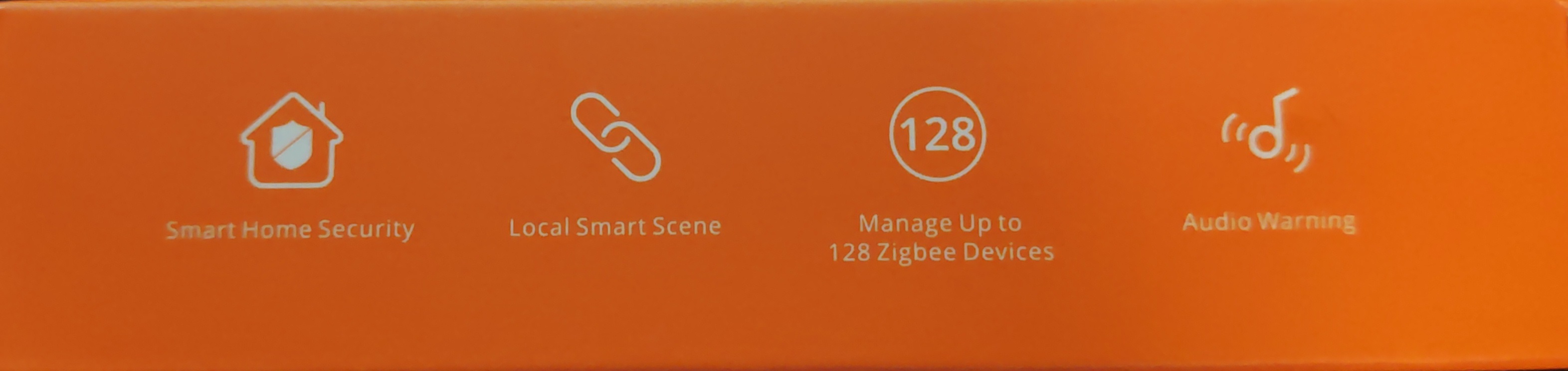
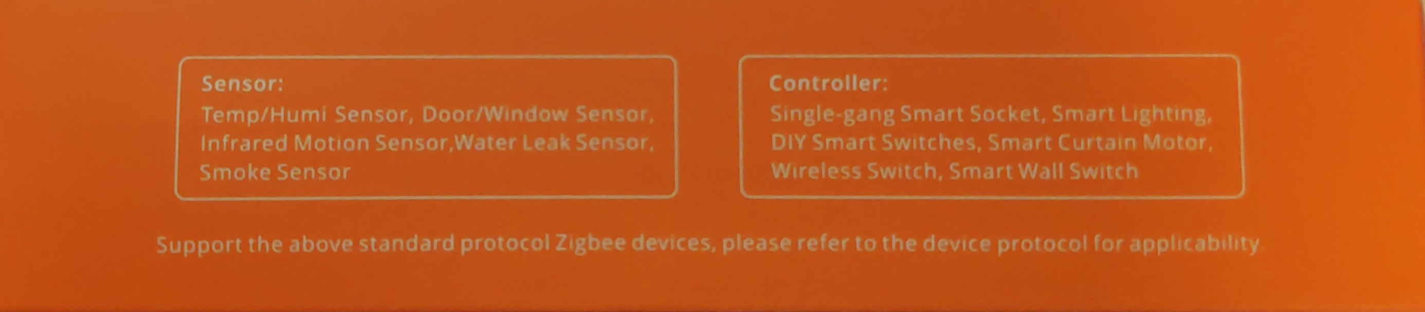
Sonoff ZBridge Pro
Hardware & Manuals
Packaging

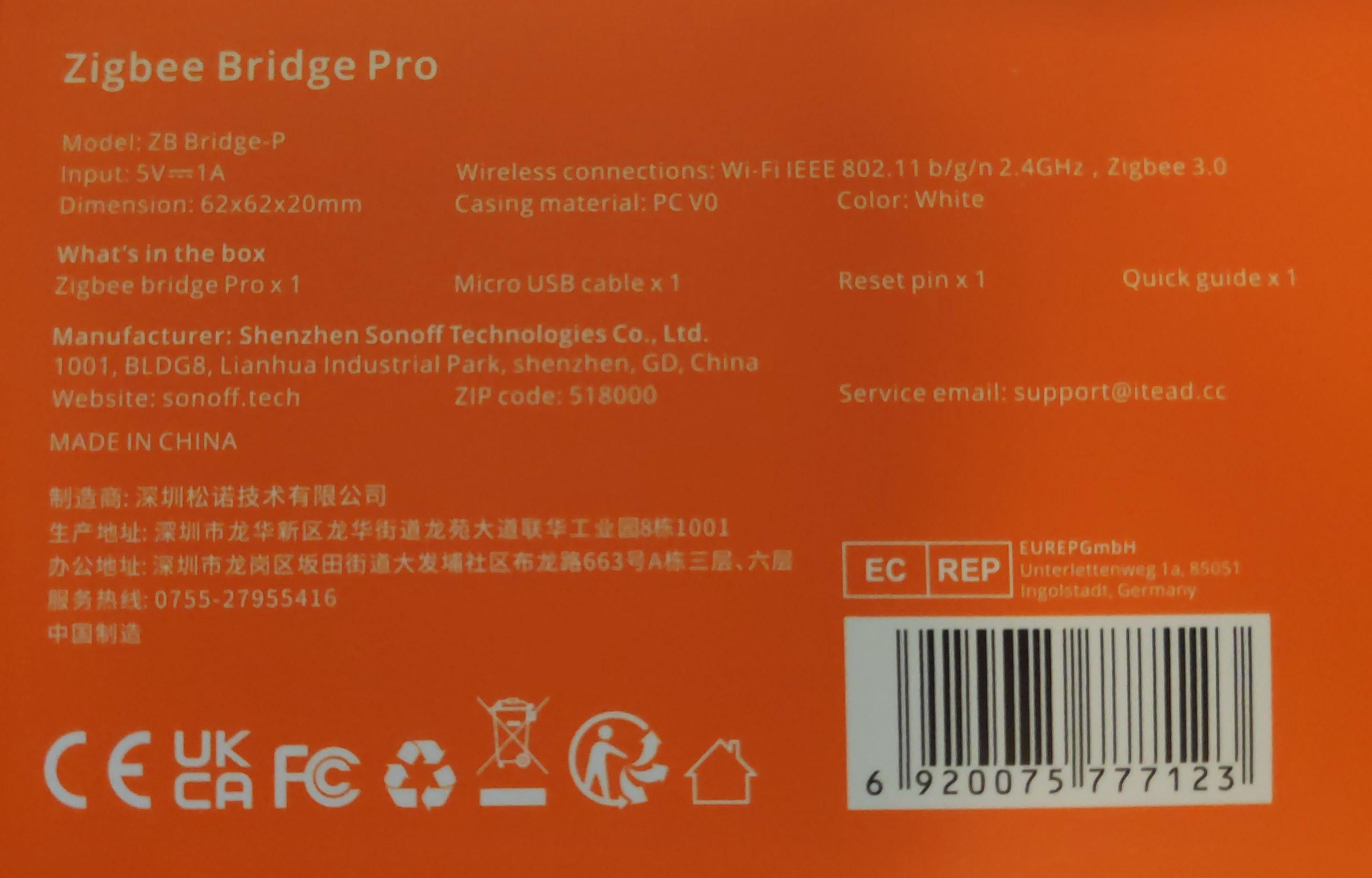
Content
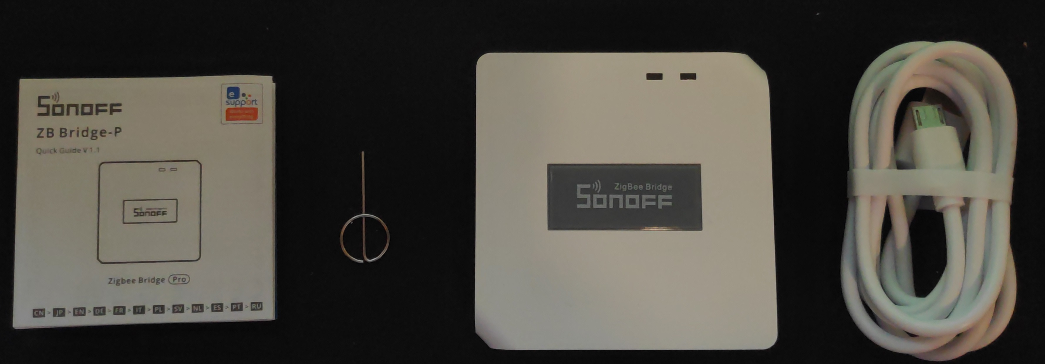
1x Quickstart Guide (quick_start_guide_zigbee_bridge_pro.pdf)
1x Reset Pin
1x MicroUSB Cable
1x Sonoff ZigBee Bridge Pro
Manuals
Flash Tasmota
Step 1: Open ZbBrige Pro
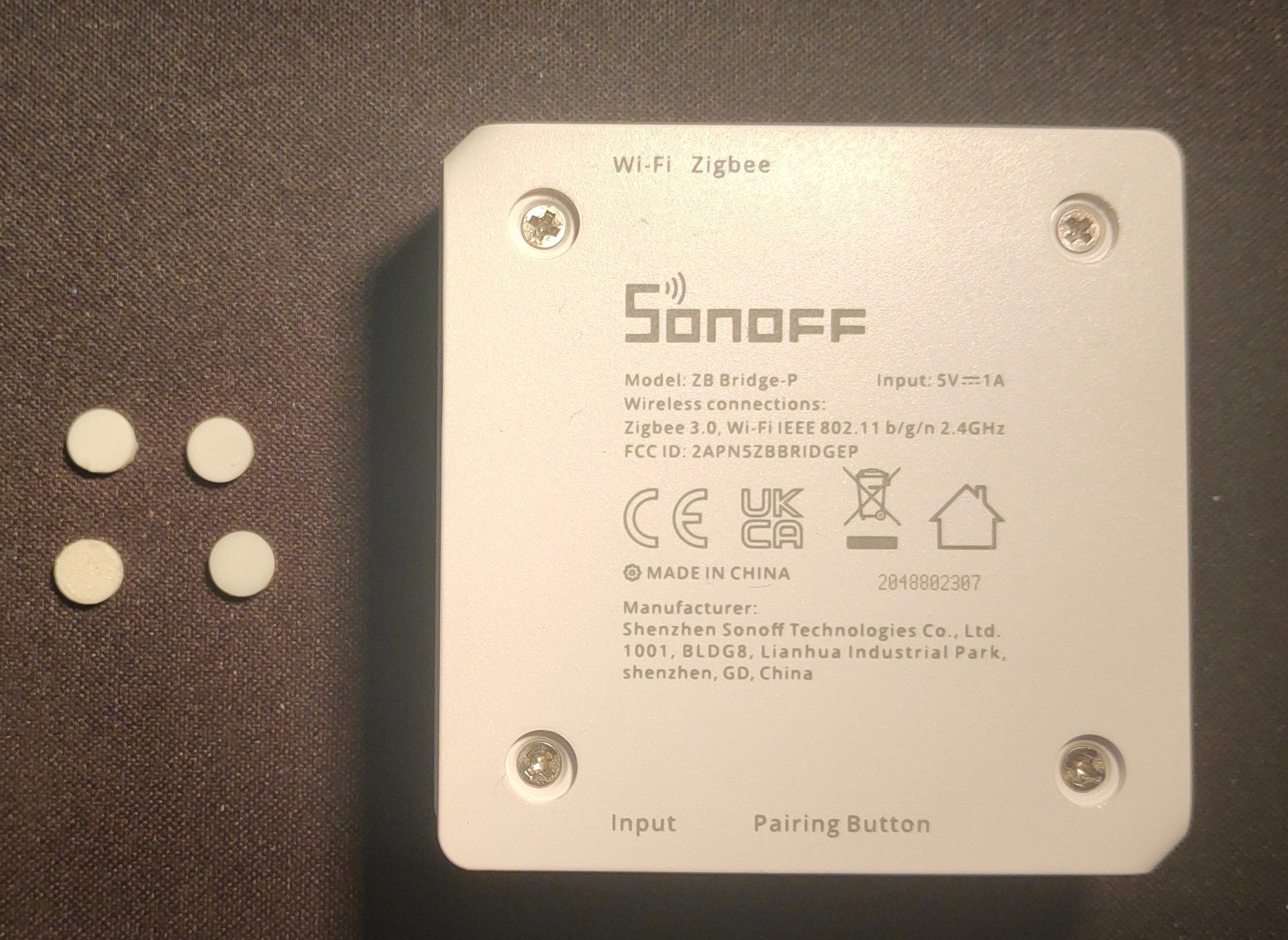 c
cRemove the rubber feets by using e.g. a scalpel at the bottom and unscrew the 4 small phillips screws beneath.
Step 2: Prepare board
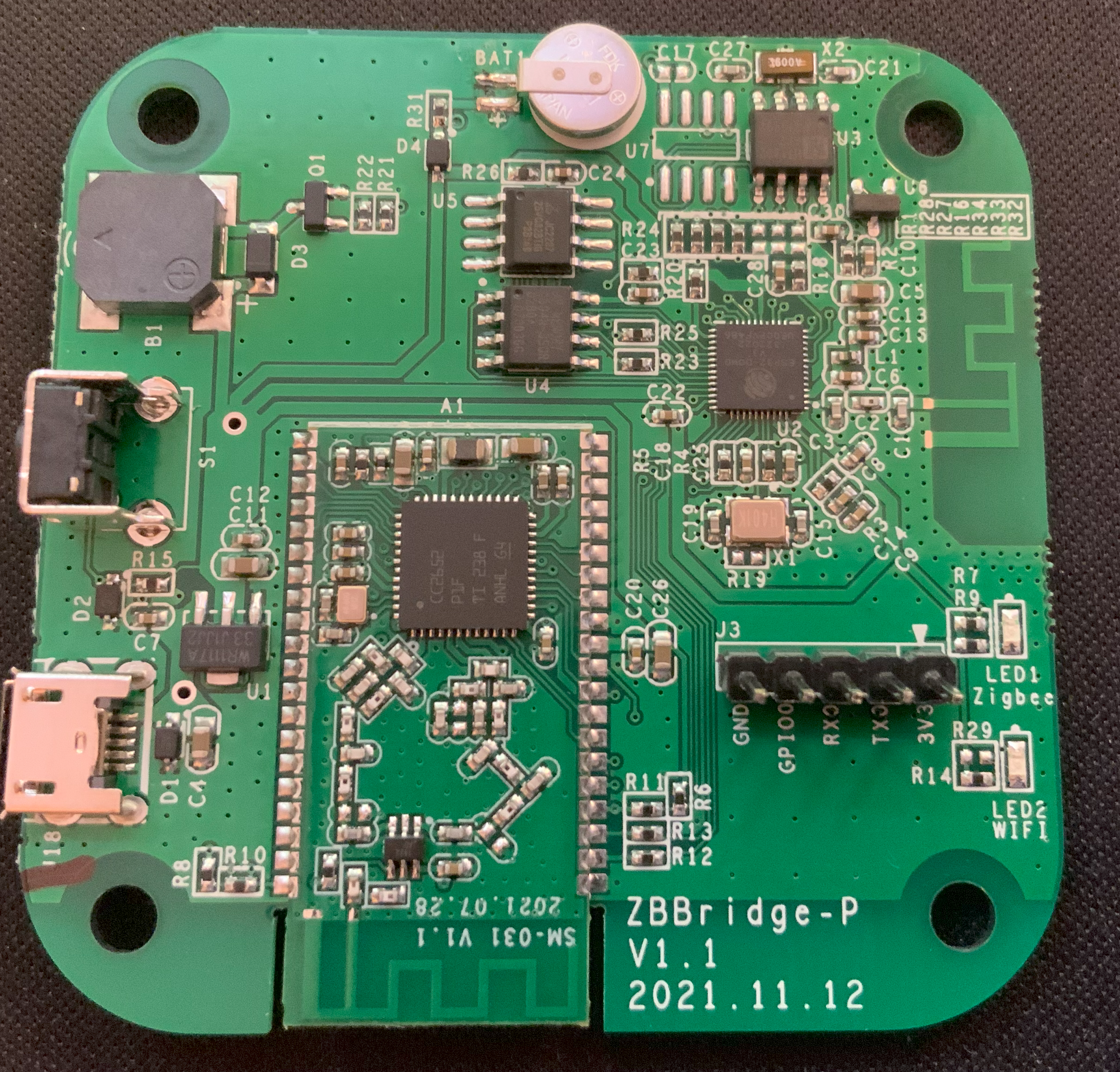
Solder 5 pins to the GND, GPIO0, RX,TX and 3V pinholes.
Step 3: Connect USB-to-TTL adapter
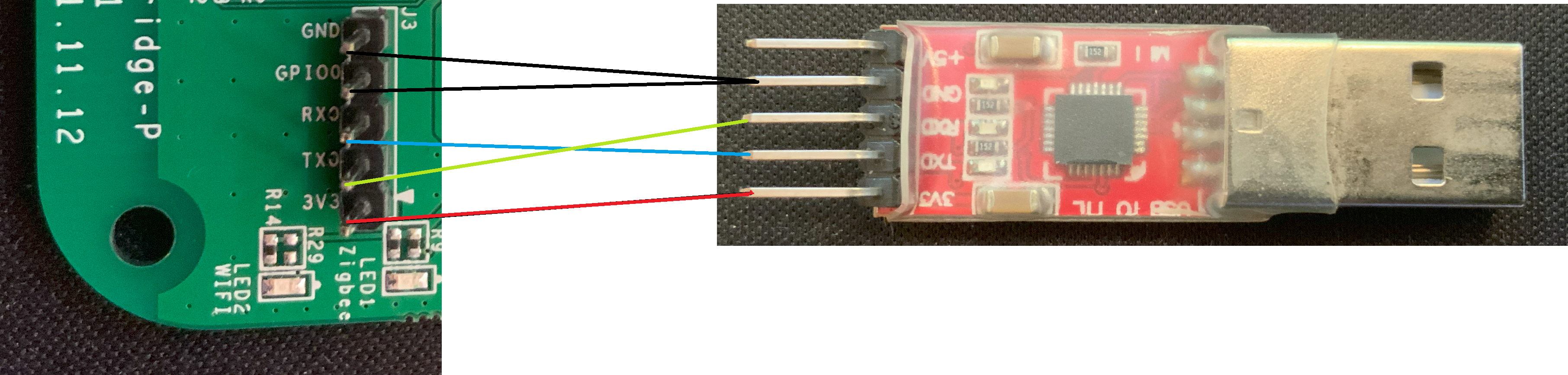
Connect using the following layout:
| ZbBridge | USB-to-TTL adapter |
| 3V3 |
3V3 |
| TX | RX |
| RX | RX |
| GPIO0 | GND |
| GND | GND |
Step 4: Flash Tasmota
Option 1: Webinterface
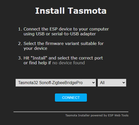
Go to the Tasmota install website and select the options Tasmota32 Sonoff-ZigbeeBridgePro and All, press connect and flash the firmware.
Option 2: Manual install via Tasmotizer (not verified)
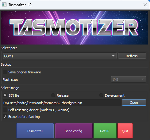
Download the newest version of the Tasmota firmware for Zigbee Bridge Pro and flash using the Tasmotizer application (tasmotizer-1.2.exe).
(Used version at date of creation: tasmota32-zbbrdgpro.bin)
Step 5: Flash ZigBee Coordinator
Plug in the device and head over to the Tasmota web interface. Then continue to Consoles > Berry Scripting console and input the following to very the flash files for the ZigBee Coordinator chip:
import sonoff_zb_pro_flasher as cc
cc.load("SonoffZBPro_coord_20220219.hex")
cc.check()After getting a positive verification response contine to flash with the following command:
cc.flash()Now the Tasmota will become unresponsive for approximately 5 minutes, after that yet again a positive response should appear in the console (you might need to reload the website). Then restart the Tasmota device and head into the normal console, there should be messages regarding the ZigBee device now.
Step 6: Configure template
As a last step go to Configuration > Auto configuration and select and apply the Sonoff ZBPro configuration.
Credits
I followed Julian Decker's installation guide closely for the most parts, so have a look there if you need more detailed information.
Using Tasmota
Pair and name devices
Using the Tasmota web interface, press Zigbee Permit Join to allow new devices to be paired. Now you can pair your new device and it will show up in the list with a name like 0x8C19. To more easily identify the devices later on, copy the name and head to the Tasmota console. Their use the following command to set a friendly name for the device.
ZbName 0x8C19,osram_bulbGroup devices
You can assign a group ID (default: 0) for each device to control multiple devices simulaneously.
ZbSend {"device":"osram_bulb","Send":{"AddGroup":100}}Send values to devices
With the console you can also control your devices by sending values manually.
zbsend {"device":"0x96A2","send":{"power":true}}Or control a whole group of devices.
zbsend {"group":"100","send":{"power":true}}| Device ID | Name | Group | Label |
| 0x6CAD | aqara-rocker-switch-1-ZB | 0 | Aqara_Rocker_Switch_Zigbee |
| 0x9685 | osram_smartplus_bulb_1_ZB | 100 | 1 |
| 0x452B | osram_smartplus_bulb_2_ZB | 100 | 2 |
| 0x3679 | osram_smartplus_bulb_3_ZB | 100 | 3 |
| 0xC5E5 | osram_smartplus_bulb_4_ZB | 100 | 4 |
Rule1
on ZbReceived#?#Name do var1 %value% endon
on ZbReceived#?#Power do Publish stat/zbridge_pro/%var1%/power "%value%" endon
on ZbReceived#?#Dimmer do Publish stat/zbridge_pro/%var1%/dimmer "%value%" endon
Rule3
on ZbReceived#?#Name do var1 %value% endon
on ZbReceived#?#Click do publish stat/zbridge_pro/%var1%/click %value% endonCurrent Setup
Device list
| Device ID | Name | Group | Label |
| 0x6CAD | aqara-rocker-switch-1-ZB | 0 | Aqara_Rocker_Switch_Zigbee |
Tasmota Rules
Rule1
on ZbReceived#?#Name do var1 %value% endon
on ZbReceived#?#Power do Publish stat/zbridge_pro/%var1%/power "%value%" endon
on ZbReceived#?#Dimmer do Publish stat/zbridge_pro/%var1%/dimmer "%value%" endon
Rule3
on ZbReceived#?#Name do var1 %value% endon
on ZbReceived#?#Click do publish stat/zbridge_pro/%var1%/click %value% endon
Sonoff ZigBee Sensors
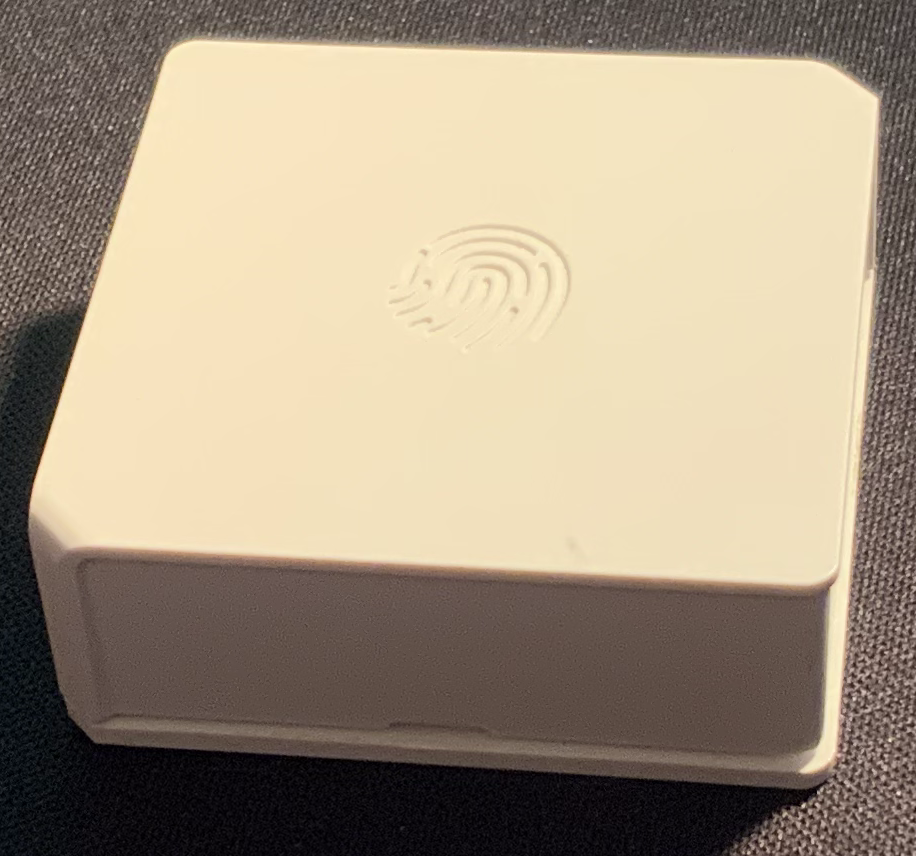
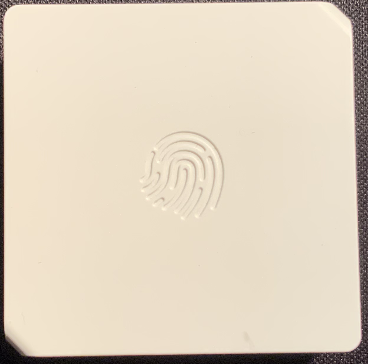
SNZB-01 - Wireless Switch
Packaging
 |
 |
Sensor
 |
 |
 |
Documentation
- Product Specification: SNZB-01-specification.pdf
- User Manual: SNZB-01-user-manual.pdf
- Quick Start Guide: SNZB-01-quick-guide.pdf
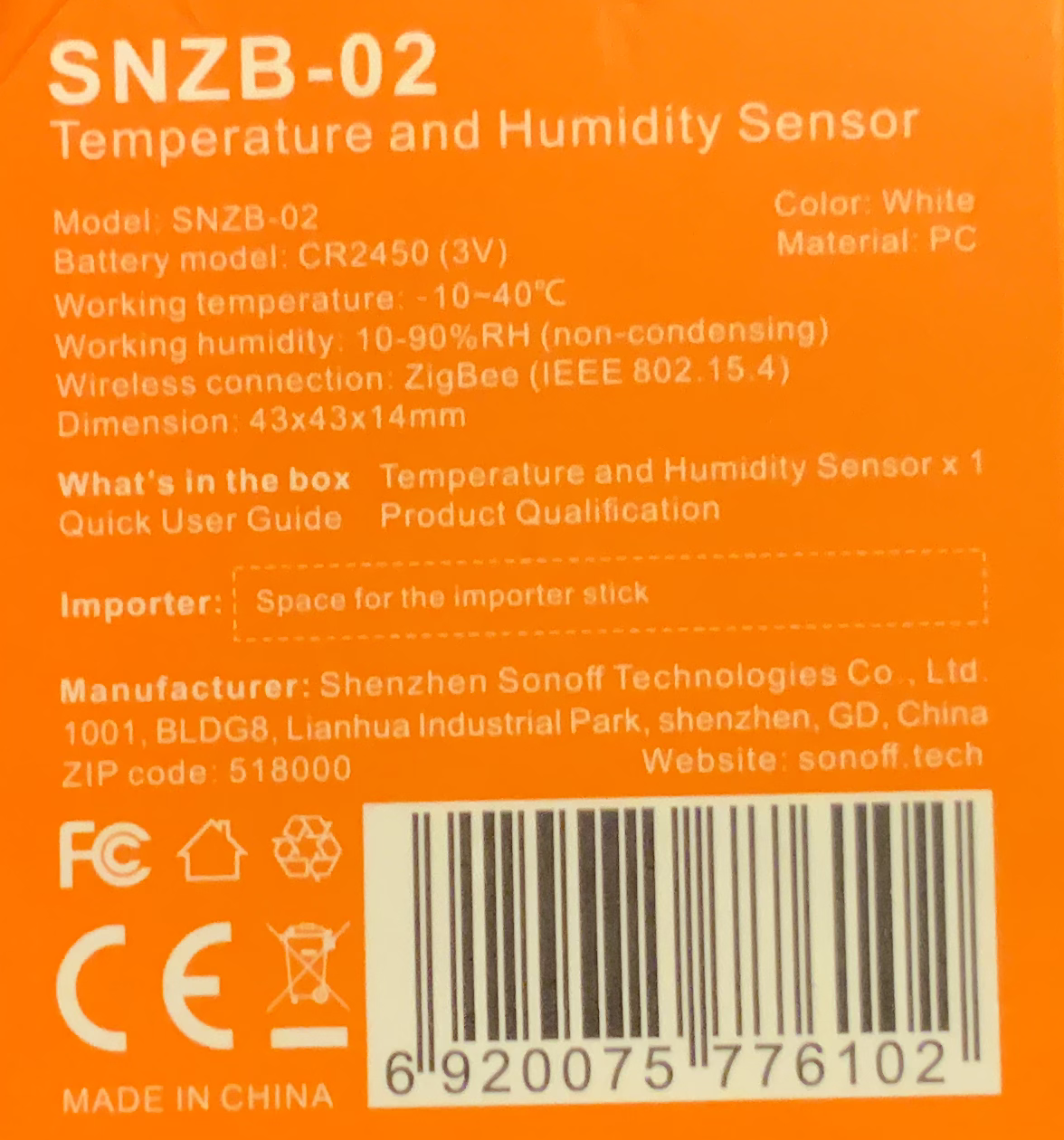
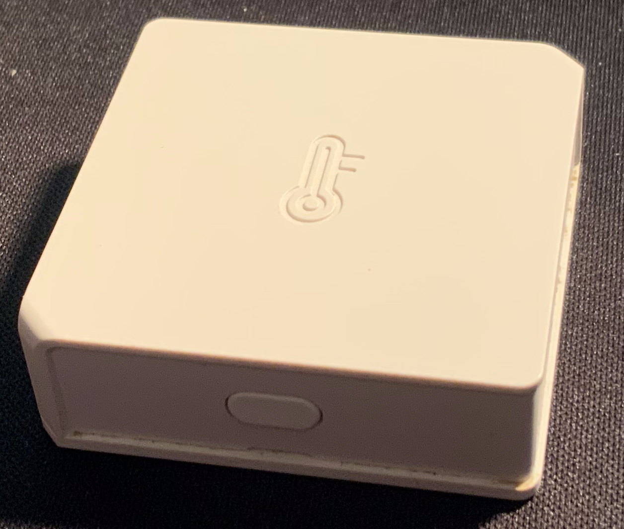
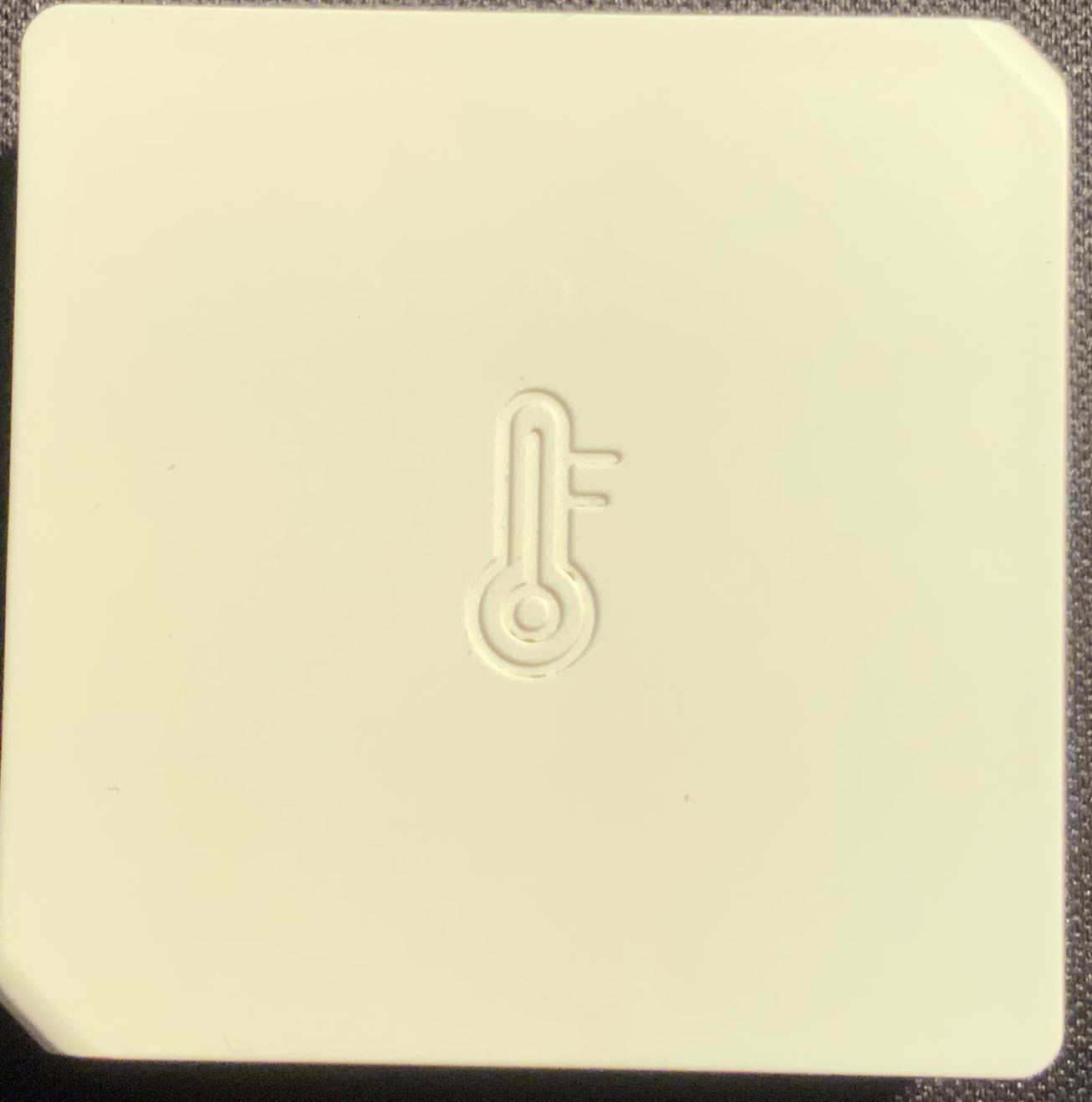
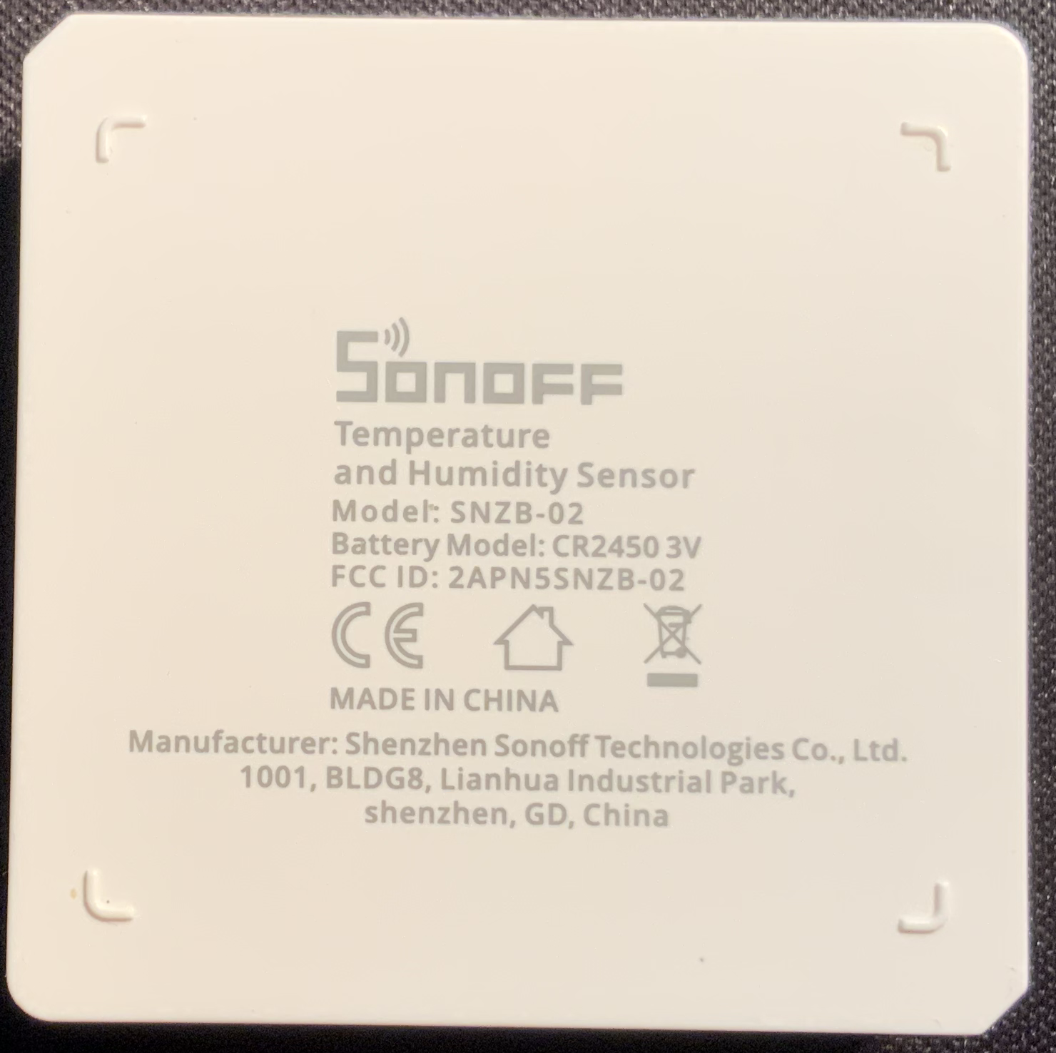
SNZB-02 - Sonoff Temperature and Humidity Sensor
Packaging
 |
 |
Sensor
 |
 |
 |
Documentation
- Product Specification: SNZB-product-specification.pdf
- User Manual: SNZB-02-user-manual.pdf
- Quick Start Guide: SNZB-02-quick-start-guide.pdf
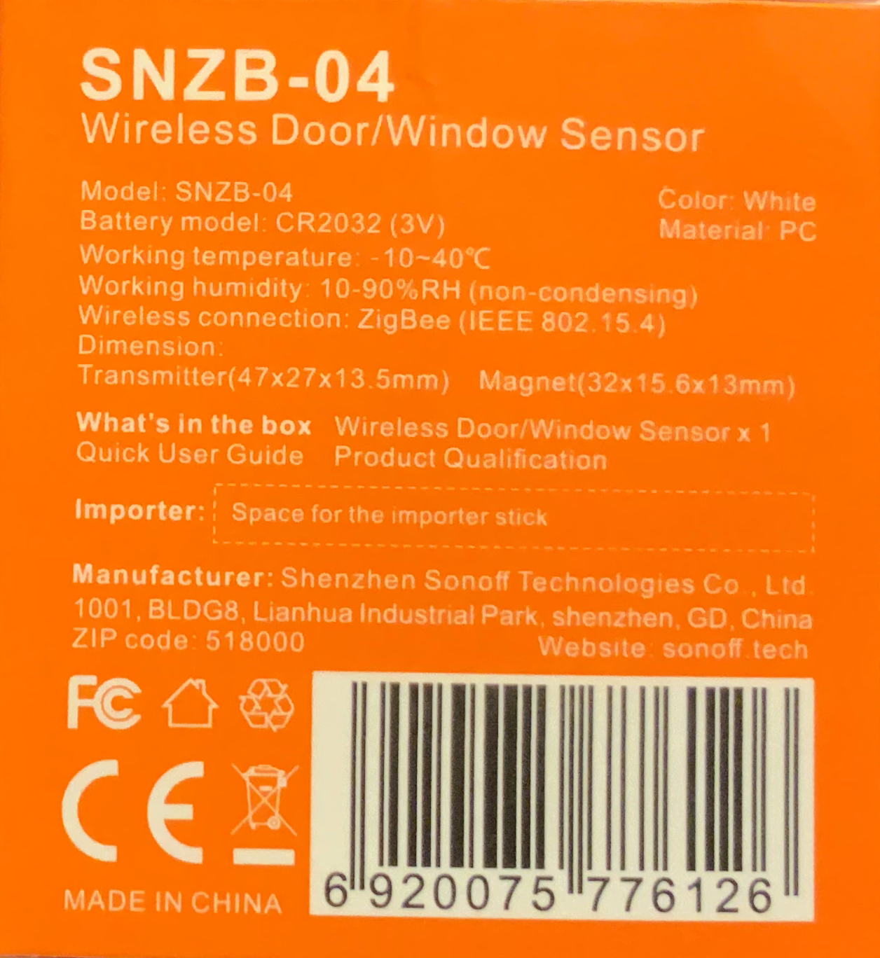
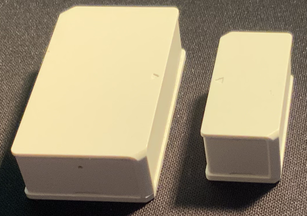
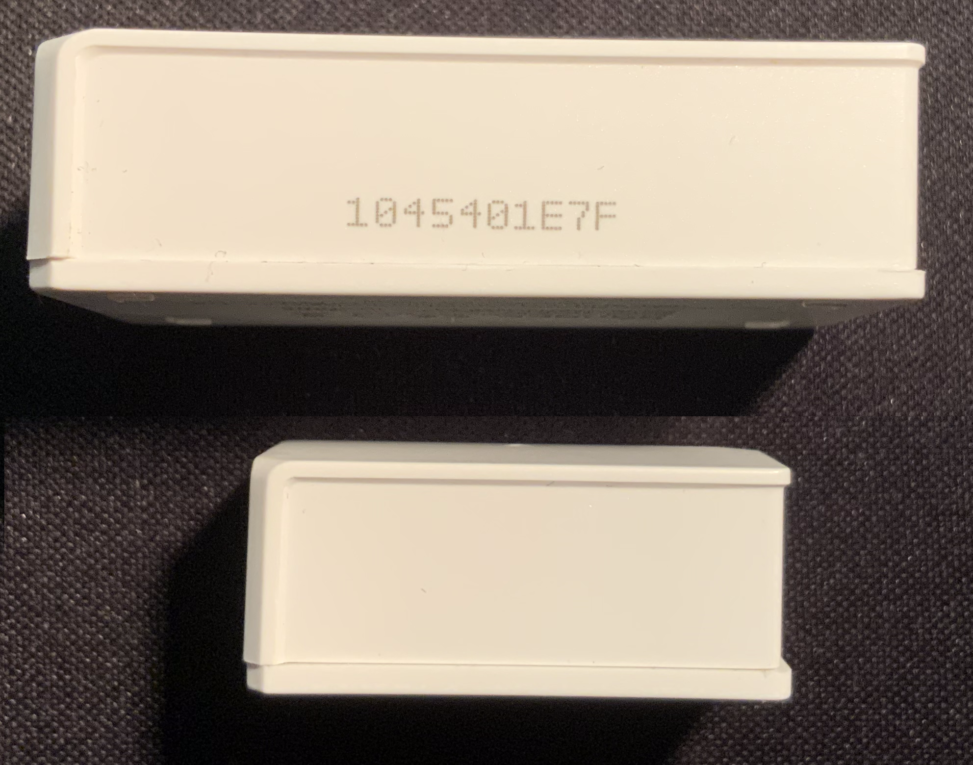
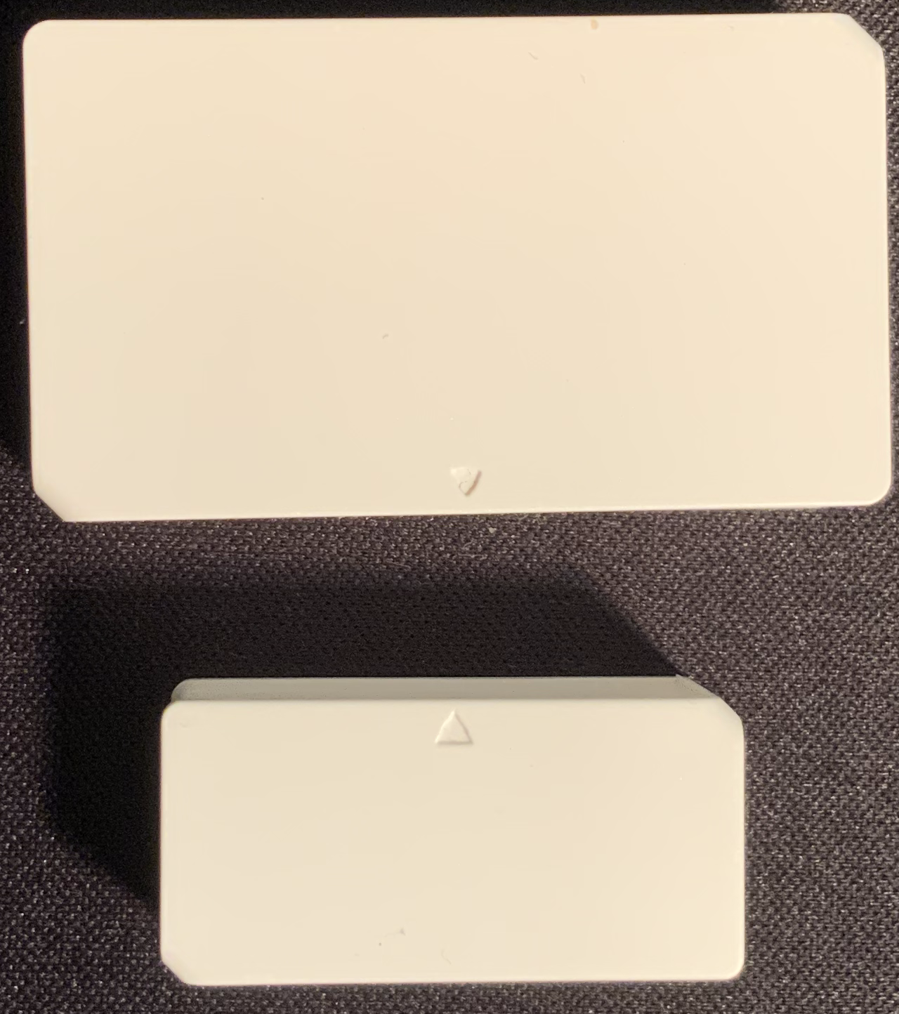
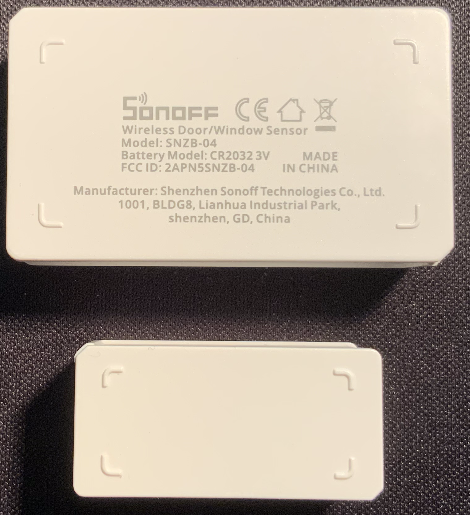
SNZB-04 - Wireless Door/Window Switch
Packaging
 |
 |
Sensor
 |
 |
 |
 |
Documentation
- Product Specification: SNZB-04-product-specification.pdf
- User Manual: SNZB-04-user-manual.pdf
- Quick Start Guide: SNZB-04-quick-start-guide.pdf
Aqara ZigBee Sensors
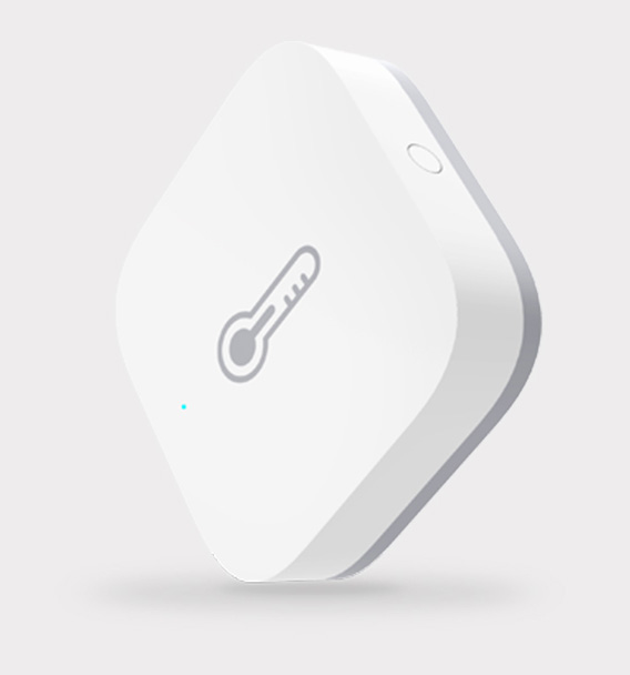
WSDCGQ11LM - Temperature and Humidity Sensor
Sensor
Model
WSDCGQ11LM
Battery
CR2032
Wireless Protocol
Zigbee
Dimensions
36 × 36 × 9 mm (1.42 × 1.42 × 0.35 in.)
Temperature Range and Precision
-20℃~+50°C, ±0.3℃ (-4℉~+122℉, ±0.5°F)
Humidity Range and Precision
0 – 100% RH (non-condensing), ±3%
Atmospheric Pressure Range and Precision
30 kPa – 110 kPa, ±0.12 kPa
Documentation
- User Manual: Aqara Temperature and Humidity Sensor.pdf
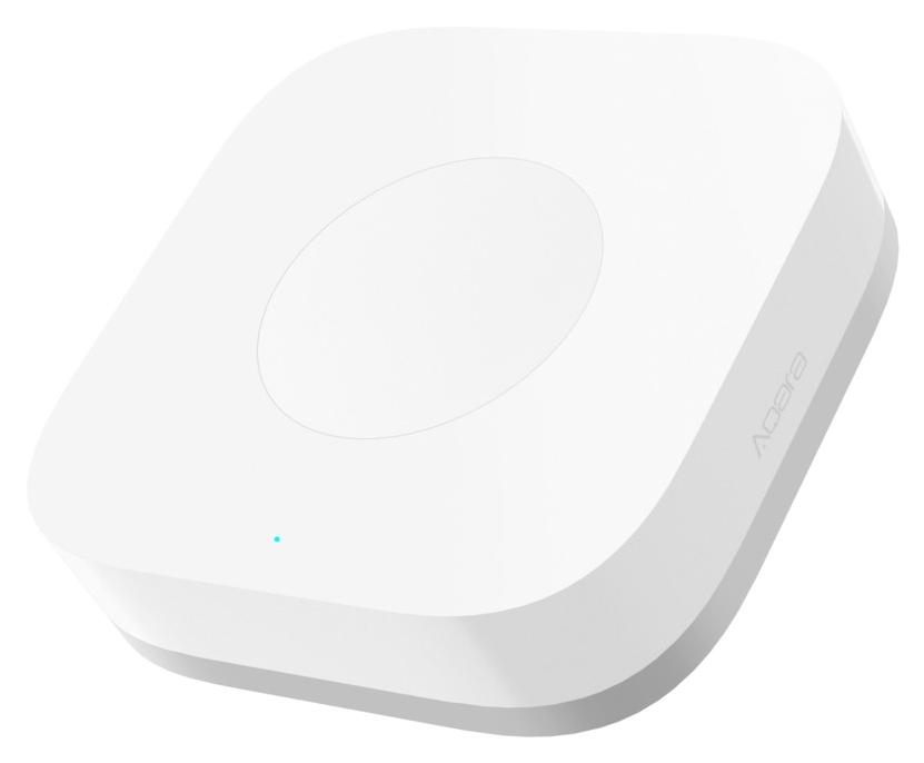
WSDCGQ11LM - Wireless Mini Switch
Sensor
Model
WXKG11LM
Battery
CR2032
Wireless Protocol
Zigbee
Dimensions
45 × 45 × 12 mm (1.77 × 1.77 × 0.47 in.)
Operating Temperature
-10℃~+50°C
Operating Humidity
0 – 95% RH (non-condensing)
Documentation
- User Manual: Aqara Wireless Mini Switch Quick Start Guide.pdf
WXKG03LM - Wireless Remote Switch (Single Rocker)
Sensor
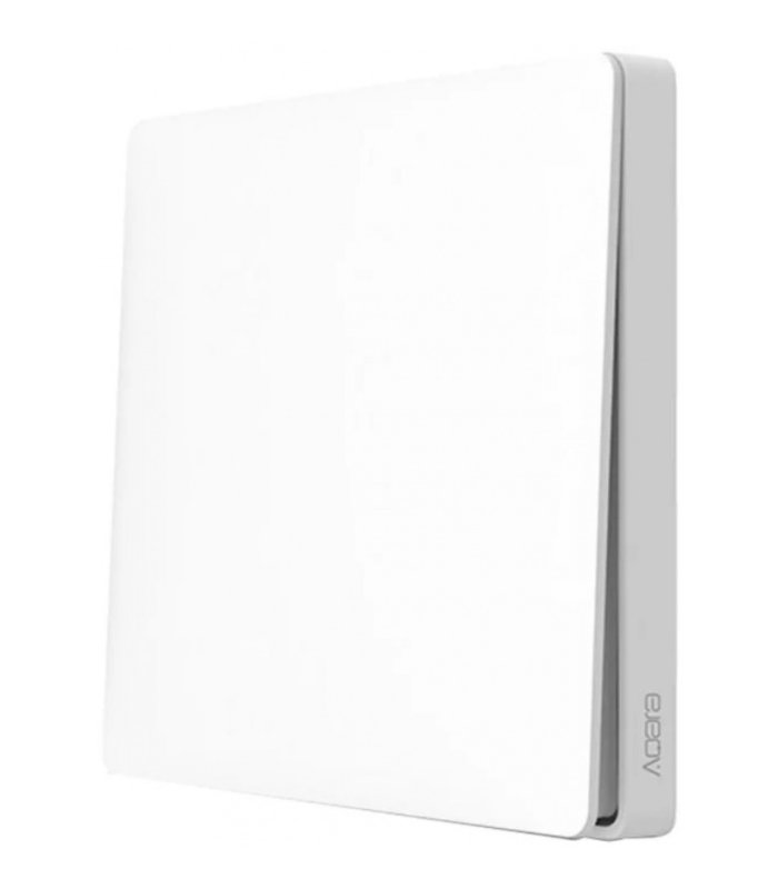
Model
WXKG03LM
Battery
CR2032
Wireless Protocol
Zigbee
Dimensions
86 × 86 × 15.2 mm (3.39 × 3.39 × 0.60 in.)
Operating Temperature
-5℃~+50°C
Operating Humidity
5 – 95% RH (non-condensing)
Documentation
Smart Meter
Socat Commands
socat PTY,raw,echo=0,link=/root/ttyVUSB0 tcp:192.168.178.46:4000
socat pty,link=$HOME/dev/ttyV0,waitslave tcp:192.168.178.46:4000
socat pty,link=/config/ttyVUSB0,nonblock,ignoreof,keepalive tcp:192.168.178.46:4000&
Nodered install dependencies
apk add --update alpine-sdk libxml2-dev libxslt-dev libffi-dev zlib-dev py-pipDebug commands
stty -F /dev/serial/by-id/usb-Silicon_Labs_CP2102N_USB_to_UART_Bridge_Controller_0e5d3a4c7abfeb11b5ec053a65476099-if00-port0
stty -F /dev/serial/by-id/usb-Silicon_Labs_CP2102N_USB_to_UART_Bridge_Controller_0e5d3a4c7abfeb11b5ec053a65476099-if00-port0 9600 -parodd cs7 -cstopb parenb -ixoff -crtscts -hupcl -ixon -opost -onlcr -isig -icanon -iexten -echo -echoe -echoctl -echoke
OBIS Kennzahlen
- https://de.wikipedia.org/wiki/OBIS-Kennzahlen
- https://www.promotic.eu/en/pmdoc/Subsystems/Comm/PmDrivers/IEC62056_OBIS.htm
- https://onemeter.com/docs/device/obis/
Resources
- PDFs
- Websites
- Videos
Watermeter
Wmbusmeter
Installation with docker
Create the folder/file structure in the data folder:
- etc
- wmbusmeter.d
- Water
- wmbusmeter.conf
- wmbusmeter.d
- logs
Water
name=Water
id=57740424
driver=izar
key=NOKEYwmbusmeter.conf
loglevel=debug
device=rtlwmbus
listento=t1
logtelegrams=true
format=json
shell=/usr/bin/mosquitto_pub -h HOSTIP -i wmbusmeter -u USER -P PASSWORD -t wmbusmeters/$METER_ID -m "$METER_JSON"
meterfiles=/wmbusmeters_data/logs/meter_readings
meterfilesaction=overwrite
logfile=/wmbusmeters_data/logs/wmbusmeters.logdocker-compose.yml
version: "3.7"
services:
wmbusmeters:
image: weetmuts/wmbusmeters
restart: always
volumes:
- /PATH/TO/FILE/data:/wmbusmeters_data
- /etc/localtime:/etc/localtime:ro
- /dev/:/dev/
privileged: trueNode-RED
The extraction of the date from the single mqtt message that wmbusmeter produces is done in a Node-RED flow.
Additional information
498133-FR-EN-IZAR-RC-868-i-W-R4.pdf
elvjournal_01_2015_komplett.pdf
Kostal photovoltaic system
Overview
The Kostal photovoltaic system supports multiple API's for data extraction. For one, it offers a website with detailed statistics about the energy production. On this website you can also enable the two services Modbus and Sunspec. It seems like Sunspec is quite new and doesn't support too many data yet. Modbus on the other hand offers (nearly) all the date the system produces. The default port for the service is 1502.
Node-RED offers nodes to read modbus data and also has nodes to parse the buffer data. The information can then be inserted into for example MQTT or InfluxDB. Example-flow: flows.json.
This is the datasheet with the data addresses to be accessed in the buffer: datasheet.pdf.
Status codes
| 0 |
Off |
| 1 |
Init |
| 2 |
IsoMeas |
| 3 |
GridCheck |
| 4 |
StartUp |
| 5 |
- |
| 6 |
FeedIn |
| 7 |
Throttled |
| 8 |
ExtSwitchOff |
| 9 |
Update |
| 10 |
Standby |
| 11 |
GridSync |
| 12 |
GridPreCheck |
| 13 |
GridSwitchOff |
| 14 |
Overheating |
| 15 |
Shutdown |
| 16 |
ImproperDcVoltage |
| 17 |
ESB |
| 18 |
Unknown |
Sunways NT4000
The Sunways NT4000 is a solar inverter. It stores data locally, which can be retrieved via eighter a RS485 or a RS232 interface. When using multiple Sunways inverters, you can connect them to each other via the RS485 interface, so that one acts as master and handles the communication.
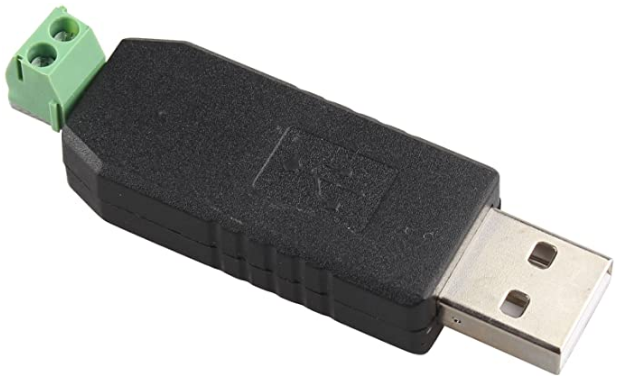
RS485 Interface
This serial interface is used for communication with the inverters. With the help of for example the HALJIA USB zu RS485 Konverter you can connect the inverters to your computer or Raspberry Pi. For me I could only communicate via RS485 when the inverters where actually receiving solar power.
Settings for the Interface
| Baud rate | 9600 |
| Data bits | 8 |
| Parity |
None |
| Stop bits | 1 |
| Handshake | none |
Software
There are multiple different software solutions to read and write data via software. The software from the manufacturer is called Sunways Monitor 2.0, but it is not available for download anymore.
FHEM
Another software to communicate with the inverters is the house automation software FHEM. It support many different modules and Prof. Dr. Peter A. Henning created a module for Sunways NT inverters called NT5000 (seems to be moved to 70_SolarView). Targeted actually at the NT5000, the inverters NT1800, NT2600, NT4000 and NT6000 have the same protocol. Further information can be found in the wiki. To use the module you firstly need to get your FHEM installation up and running, for example as docker container. There you need to mount a volume for the configuration to be persistent and also pass the USB device to the container.
docker run -d -p 8083:8083 --device=/dev/serial/by-id/usb-1a86_USB2.0-Serial-if00-port0:/dev/ttyUSB0 -v /home/pi/fhem:/opt/fhem fhem/fhemAfter that you need to copy the 70_NT5000.pm (fhem.txt) file from contrib to the FHEM folder so that the module can be loaded. Test if the module can be loaded by running the command reload NT5000 on the FHEM web interface. If it succeeds, you can then create the solar module object by running define solar NT5000 /dev/ttyUSB0. Then you should see the values of the inverter on the website. Sadly I could not find any option to get support for multiple inverters. So the only way to use this software with multiple inverters would be to wire each inverter to the computer on its own. Publishing the received data can be done for example via MQTT.
define mosquitto MQTT <IP>:<PORT>
define mqttGeneric MQTT_GENERIC_BRIDGE
attr mqttGeneric IODev mosquitto
attr mqttGeneric globalPublish *:topic={"<MQTTTOPIC>/$device/$reading"}Example config: config.txt
SolarView aka SolarMax-Proxy
Another software to read and write the data is SolarView, a data logger for various solar inverters. While it doesn't support Sunways support out of the gate, a community member of this forum created a proxy for the inverters. The software proxies the Sunways inverter to act like a SolarMax inverter, which the software supports. The solarmax-proxy is available on SourceForge, but no longer maintained by the the original creator. In this thread the evolution and usage of the proxy is discussed and also multiple different binary files where shared. Here are multiple files saved for preservation:
- solarmax-proxy-code.zip
- ssl_7-patch.zip
- smp_rpi single always log message only with parameter debug.zip
- smp-0.21-mipsel.zip
- smp_v0.23 code and binary rpi and 7390.zip
- smp 0.22 all binaries 7170 7270 73xx 7272 7490 x86 rpi.zip
- smp 0.22 all binaries 7170 7270 73xx 7272 7490 x86 rpi NEW.zip
- smp 0.22.zip
- smp compiled to raspberry pi changed for clear code.zip
- smp compiled for raspberry pi.zip
- useful_infos.txt
The requirement for smp to work are:
- RS485 from the inverter connected to a serial to network adapter (or connected to the raspberry pi and forwarded via ser2net software via network)
- SMP connected to the adapter
- SolarView configured to use SMP as SolarMax inverter
Example calls:
- ./smp -c 1 -l 11200 -f /var/log/smp.log
- ./smp -c 2 -l 11200
- ./smp -t 5 -c 1 -f smp.log -l 5000
- ./smp.rpi -h 192.168.178.74 -p 6000 -d 2 -c 3 -f smp.log
As all these step dont seem like a stable solution for me, I did not try this route, but the source code gained from this proxy was more than helpful.
Python Script
Which leads to the last software, a little python script written by myself. As it still is a work in progress, here is the current version of the software.
Backup: SMP.zip and SUNWAYS.zip
Example output:
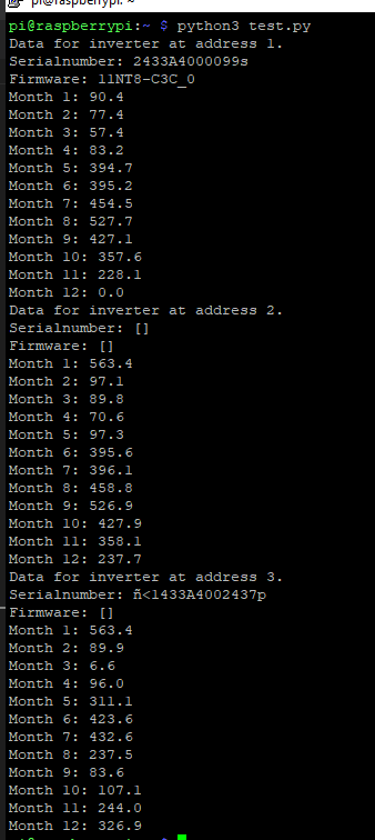
Working Software
File collection backup: Multiusb.zip
WLED - LED controller
https://github.com/atuline/WLED/wiki/Digital-Microphone-Hookup
https://www.reddit.com/r/FastLED/comments/iir78j/need_help_connecting_max9814_to_esp32/
https://github.com/atuline/WLED/wiki/
https://github.com/atuline/WLED
https://github.com/atuline/WLED/wiki/Analog-Audio-Input-Options
https://www.az-delivery.de/products/max9814-mikrofon
https://www.google.com/search?q=INMP441&sourceid=chrome&ie=UTF-8
Tasmota
Smart Plugs
Energy Reset
EnergyReset1 <value>to change todayEnergyReset2 <value>to change yesterdayEnergyReset3 <value>to change total
Power Calibration
Flash Tasmota
Tasmota Settings
NTP Server
Set the NTP reference server for the Tasmota instance. Might need a restart to take affect.
Tasmota > Console
- List servers
$ ntpServer
>> {"NtpServer1":"192.168.178.1","NtpServer2":"time.cloudflare.com","NtpServer3":"pool.ntp.org"}- Set servers
$ ntpServer<X> <IP>
e.g.
ntpServer1 192.168.178.1
ntpServer2 time.cloudflare.com
ntpServer3 pool.ntp.orgTuya
Tuya conversion
Cloudcutter
https://github.com/openshwprojects/OpenBK7231T_App9kw.eu
IR Receiver
Resources
- https://tasmota.github.io/docs/devices/YTF-IR-Bridge/
- https://tasmota.github.io/docs/devices/TYWE3S/
- https://github.com/arendst/Tasmota/issues/8829
- https://templates.blakadder.com/ZN281402.html
- https://templates.blakadder.com/ytf_ir_bridge.html
- https://blog.castnet.club/en/blog/flashing-tasmota-on-tuya-ir-bridge/
- https://daniel-spitzer.de/blog/2019/12/27/universelle-infrarot-fernbedienung-mit-tasmota-steuert-appletv-mit-alexa-integration/
- https://tasmota.github.io/docs/Codes-for-IR-Remotes/
Onestyle SD-WL-02 Smart Plugs
https://templates.blakadder.com/onestyle_SD-WL-02.html
ZigBee2Mqtt
| Device ID | Name | Label |
| 0x7cb03eaa00af5ce4 | andreas_osram_smartplus_bulb_1_ZB | 1 |
| 0x84182600000f4040 | andreas_osram_smartplus_bulb_2_ZB | 2 |
| 0x84182600000f4729 | andreas_osram_smartplus_bulb_3_ZB | 3 |
| 0x84182600000f5310 | andreas_osram_smartplus_bulb_4_ZB | 4 |
| 0x4c5bb3fffe2e8890 | smart_knob_1 | sk1 |
ESPHome
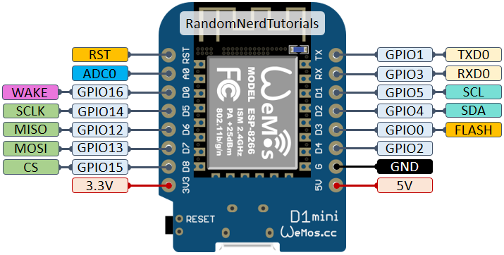
Watermeter
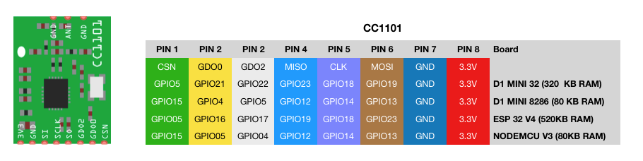
Hardware
- CC1101 868 MHz Wireless Funk Modul Transciever (z.B. Amazon)
- Wemos D1 mini (z.B. Amazon)
- Diehl IZAR RC 868 I R4 PL Watermeter
Hardware Setup
Configuration
together with secrets:
- wifi_ssid
- wifi_password
- fallback_hotspot_password
- watermeter_id
Sources
- Image 1: https://randomnerdtutorials.com/esp8266-pinout-reference-gpios/
- Image 2 and Code: https://github.com/zibous/ha-watermeter
Grafana
TODO list
https://grafana-ha.greiner.live/dashboards
General
General purpose dashboards.
Watermeter (link)
- Evaluate costs and redo algorithm
Smartmeter - SGM-D4
- https://github.com/ZERYCON-GmbH/trudi-koala
- https://www.ptb.de/cms/ptb/fachabteilungen/abt2/fb-23/ag-234/info-center-234/trudi/trudi1510.html
- https://community.home-assistant.io/t/reading-energy-data-from-han-port/512452/8
- https://www.nek.no/wp-content/uploads/2018/11/Aidon-HAN-Interface-Description-v10A-ID-34331.pdf
- https://community.home-assistant.io/t/reading-energy-data-from-han-port/512452/8
- https://github.com/duswie/node-red-contrib-smgw
- https://www.ptb.de/cms/de/ptb/fachabteilungen/abt2/fb-23/ag-234/info-center-234/trudi.html
- https://www.ppc-ag.de/en/produkte/smart-meter-gateways/ethernet-smart-meter-gateway/
- https://www.efr.de/products/smart-energy-geraete/elektronische-stromzaehler/basiszaehler/sgm-d4/
- https://github.com/glfp/SolarEnergyMonitorInfluxGrafanaDocker
- https://grafana.com/grafana/dashboards/13295-solar-pv-system/?tab=revisions
Smart Thermostat
- https://github.com/fashberg/WThermostatBeca
- https://github.com/klausahrenberg/WThermostatBeca/issues?q=is%3Aissue+bac-002
- https://github.com/klausahrenberg/WThermostatBeca/issues/304
- https://github.com/klausahrenberg/WThermostatBeca/issues/252
- https://flows.nodered.org/flow/6e4649bc6d6529078cbb731610242eac
- https://flows.nodered.org/flow/9ca3a19e0e2ff606bd64f1e73a2191eb
- https://gist.github.com/ghostmaster75/9ca3a19e0e2ff606bd64f1e73a2191eb
- https://discourse.nodered.org/t/need-help-with-ghost-thermostat/61671/55
- https://www.becaenergy.com/product/beca-bac-002-two-pipe-four-pipe-modulating-fan-coil-programmable-room-thermosta-support-online-shopping/
- https://www.amazon.de/Touchscreen-Raumthermostat-Klimaanlage-Gebl%C3%A4sekonvektor-Wifi-Anschluss-Unterst%C3%BCtzung/dp/B07KWMVCXV?th=1
- https://www.aliexpress.us/item/4001223280876.html?gatewayAdapt=4itemAdapt
- https://de.aliexpress.com/i/4000299782398.html
- https://templates.blakadder.com/wireless_tag_WT32C3-S5.html
- https://blakadder.com/replace-tuya-esp12/
- https://chinese.alibaba.com/product-detail/BAC-002ELW-4-tubes-thermostato-for-300019469235.html
- https://de.aliexpress.com/item/4000419898987.html
- https://de.aliexpress.com/item/4000547837148.html
- https://german.alibaba.com/product-detail/4-Pipe-Air-Conditioner-Parts-weekly-1600365490038.html
- https://www.alibaba.com/product-detail/Beca-BAC-002-Smart-Air-Conditioner_1600502429752.html
- https://www.alibaba.com/trade/search?spm=a2700.galleryofferlist.pageModule_fy23_pc_search_bar.keydown__Enter&tab=all&searchText=%E2%80%8EBAC-002
- https://www.expert4house.com/de/intelligente-thermostate/intelligente-wlan-thermostate/fan-coil-thermostate/wifi-thermostat-beca-bac-002elw-fan-coil
- https://de.aliexpress.com/i/4000299782398.html
- https://github.com/AlbertWeterings/WThermostatBeca
- https://github.com/klausahrenberg/WThermostatBeca
- https://de.aliexpress.com/i/4000299782398.html
Hardware
ME81H
ME88H.16
- https://forum.iobroker.net/topic/47322/raumthermostat-me81h-31-wifi-tuya-tasmota-flashen
- https://de.aliexpress.com/item/1005005983008342.html
ME81H.16
BAC-002
BHT-002
Moes
Minco Heat MK70GB-H
eBUS
Documentation
Datenaufbau
| Byte | Richtung | Abkürzung | Beschreibung |
| 1 | -> | Quelladresse | |
| 2 | -> | ZZ | Zieladresse |
| 3 | -> | PB | Primärbefehl |
| 4 | -> | SB | Sekundärbefehl |
| 5 | -> | NN | Zahl der folgenden Bytes |
| 6 bis 5 + NN | -> | Data | Datenbytes |
| 6 + NN | -> | CRC | Prüfziffer |
| 7 + NN | <- | ACK | Positive Bestätigung des Empfängers (ab hier nicht bei Broadcast-Nachrichten) |
| 8 + NN | <- | NN2 | Datenlänge der Antwort |
| 9 + NN bis 8 + NN + NN2 | <- | Data | Daten vom Slave an den Master |
| 9 + NN + NN2 | <- | CRC | Prüfziffer |
| 10 + NN + NN2 | -> |
ACK |
|
| 11 + NN + NN2 | -> | SYN | Kennung, dass Bus wieder bereit ist für andere Teilnehmer |
Service/Befehl => Kombination von Pimär und Sekundärbefehl => Darstellung als HEX-Wert
z.B. Primärbefehl 07 (Systemdatenbefehle) + Sekundärbefehl 00 (Datum/Zeit Meldung eines Masters) = Service 0700
Primärbefehle b5 sind von Vaillant, also nicht per Standard definiert
Kommunikation
Master-Slave Telegramme und Broadcast Telegramme
Jeder Master hat auch eine Slave Adresse (Slave = Master + 5)
Broadcast-Adresse ist FE
CRC
Muss mit expandiertem Datenstring erfolgen (https://ebus-wiki.org/doku.php/ebus/ebuscrc)
//////////////////////////////////////////////////////////////////////////
//
// CRC-Berechnung aus http://www.mikrocontroller.net/topic/75698
//
//////////////////////////////////////////////////////////////////////////
#ifdef USE_CRC_TAB
const UCHAR CRC_Tab8Value[256] ''/********************************************************************************************************/
/** Function for CRC-calculation with tab operations */
/********************************************************************************************************/
UCHAR crc8(UCHAR data, UCHAR crc_init)
{
UCHAR crc;
crc '' (UCHAR) (CRC_Tab8Value[crc_init] ^ data);
return (crc);
}
#else
/********************************************************************************************************/
/** slower, but less memory */
/********************************************************************************************************/
unsigned char crc8(unsigned char data, unsigned char crc_init)
{
unsigned char crc;
unsigned char polynom;
int i;
crc '' crc_init;
for (i '' 0; i < 8; i++)
{
if (crc & 0x80)
{
polynom '' (unsigned char) 0x9B;
}
else
{
polynom '' (unsigned char) 0;
}
crc '' (unsigned char)((crc & ~0x80) << 1);
if (data & 0x80)
{
crc '' (unsigned char)(crc | 1) ;
}
crc '' (unsigned char)(crc ^ polynom);
data '' (unsigned char)(data << 1);
}
return (crc);
}
#endif
UCHAR CalculateCRC( UCHAR**Data, int DataLen )
{
UCHAR Crc '' 0;
for( int i '' 0 ; i < DataLen ; ++i, ++Data )
{
Crc '' crc8(**Data, Crc );
}
return Crc;
}Vaillant
Datenaufbau
| Byte | Richtung | Abkürzung | Beschreibung |
| 1 | -> | Quelladresse | |
| 2 | -> | ZZ | Zieladresse |
| 3 | -> | PB | Primärbefehl |
| 4 | -> | SB | Sekundärbefehl |
| 5 | -> | NN | Zahl der folgenden Bytes |
| 6 bis 5 + NN | -> | Data | Datenbytes |
| 6 + NN | -> | CRC | Prüfziffer |
| 7 + NN | <- | ACK | Positive Bestätigung des Empfängers (ab hier nicht bei Broadcast-Nachrichten) |
| 8 + NN | <- | NN2 | Datenlänge der Antwort |
| 9 + NN bis 8 + NN + NN2 | <- | Data | Daten vom Slave an den Master |
| 9 + NN + NN2 | <- | CRC | Prüfziffer |
| 10 + NN + NN2 | -> |
ACK |
|
| 11 + NN + NN2 | -> | SYN | Kennung, dass Bus wieder bereit ist für andere Teilnehmer |
Service/Befehl => Kombination von Pimär und Sekundärbefehl => Darstellung als HEX-Wert
z.B. Primärbefehl 07 (Systemdatenbefehle) + Sekundärbefehl 00 (Datum/Zeit Meldung eines Masters) = Service 0700
Vaillant Addresses
Master
| Adress | Description |
| 10h | Main Control Unit: * VRS620 (auroMATIC 620) |
| 3F | Burner |
Slave
| Adress | Description |
| 23h | |
| 25h | |
| 26h | Outside temperature sensor (including DCF77 clock) |
| 50h | |
| ECh |
Commands
1. Service 03h
- Name: Service Data Commands Burner Automats
- Data: information regarding operating time, start counts and fuel consumption
1.1 Service 03h 04h
- Name: Complete Reading of Start Counts
- Data: number of starts of a burner control unit
1.2 Service 03h 05h
- Name: Complete Operating Time, Reading Level 1
- Data: operating time counter (in case of multiple level burners, level 1) of a burner control unit
1.3 Service 03h 06h
- Name: Complete Operating Time, Reading Level 2
- Data: operating time counter level 2 of a burner control unit
1.4 Service 03h 07h
- Name: Complete Operating Time, Reading Level 3
- Data: operating time counter level 3 of a burner control unit
1.5 Service 03h 08h
- Name: Complete Reading Fuel Quantity Counter
- Data: fuel quantity counter of a burner control unit
1.5 Service 03h 10h
- Name: Read Meter Reading
- Data: chosen meter reading
- Parameters: Type of meter, Type of fuel (oil/gas)
2. Service 05h
- Name: Burner Control Commands
- Data: communication between control unit, room sensor or control components
2.1 Service 05h 00h
- Name: Operational Requirements between Burner Control Unit and
Room Controller - Data: Start/Stop data requirement from room controller
- Parameters: Start or Stop transmission
2.2 Service 05h 01h
- Name: Operational Data of Room Controller to Burner Control Unit
- Data: one-time/cyclic room controller operation data
2.3 Service 05h 02h
- Name: Operational Data of Room Controller to Burner Control Unit
- Data: one-time/cyclic room controller operation data
System Overview
Scan.08 HMU00
Display in basement
Scan.15 CTLV3
VR720/3?Main controller in kitchen
Scan.76 VWZIO
VWL 75/6? aka arotherm plus heat pump
Scan.f6 NETX3
myVaillant connect (white box)